Design Guidelines for Plastic Thermoformed Parts – Top 13 Tips for Plastic-Optimized Construction
Plastic thermoforming is shaped by factors like material quality, temperature, pressure, speed, and tool geometry. With the right design principles, you can prevent errors in CAD and production. formary has gathered key tips to help you optimize your thermoformed parts.
Sarah Guaglianone
Updated on June 24, 2026
Share
Contents
Design guidelines for the manufacture of plastic thermoformed parts – Key points at a glance
Radii & draft angles: Large radii (at least 1.5 mm) and draft angles (>2°) facilitate deep drawing and prevent creasing and material tears.
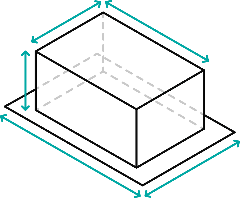
Forming ratio & wall thickness: The ratio of height to width affects material stretching; the initial thickness and the desired wall thickness must be calculated at an early stage.
Thermoforming-friendly geometry: Take into account transitions, undercuts, tolerances and material shrinkage to optimise quality, demouldability and production costs.
→ Do you already have CAD data that you’d like to check for deep-drawability? Click here for the DfM analysis
What are the key design principles to follow when designing deep-drawn parts?
The key design rules for plastic deep-drawn parts are:
sufficiently large radii to prevent cracks
Wall angles for safe demoulding
a suitable forming ratio for controlling the wall thickness
reduced undercuts for easy manufacturing
design tailored to the material to prevent warping
If these design guidelines for plastic deep-drawing are followed, quality, costs and process reliability can be significantly improved. You will find more details on this in the following sections.
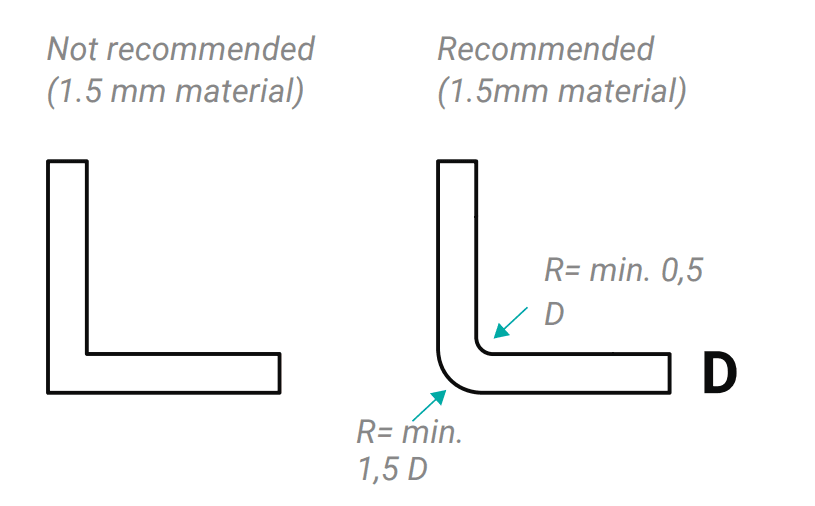
1. Design Rule: Radii in Plastic Thermoforming
When designing plastic parts, it is important to always incorporate the largest possible radii in order to improve stretchability. Deep-drawn parts should always be manufactured with a minimum radius of 1.5 mm.
When it comes to the tool side, a minimum radius is required; as a very rough rule of thumb (since this depends on many parameters), this should not be less than the original thickness of the material.
Dealing with sharp edges
If sharp edges are required, ensure that the design of the plastic parts includes a fillet radius that is at least as large as the original thickness of the material. If the fillet radius is set smaller, the parts cannot be deep-drawn, or can only be done so with great difficulty. Furthermore, costs will increase due to longer tool milling times.
Note: The radii appear even larger on the deep-drawn part than on the die itself. For both positive and negative dies, when specifying the smallest possible radii, the key consideration is to ensure that the material fits as snugly as possible into the corners. The radius on the side facing away from the die is determined by the radius of the die side, as well as the material type, the material stretch and the material thickness.
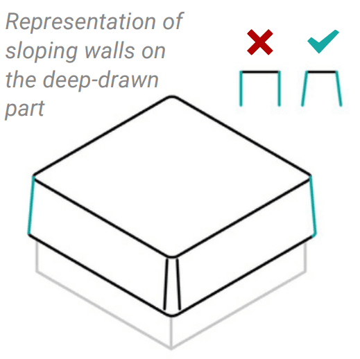
2. Design Rule: Draft Angles
The angle between the vertical part wall and the direction of demoulding is known as the demoulding angle. As the choice of demoulding angles affects the geometry of the deep-drawn part, the angles of the demoulding angles must be determined at an early stage and incorporated into the design data.
Design vertical walls with draft angles to ensure easy demolding without visible surface defects.
ℹ️ Recommended Draft Angles:
General recommendation: >2°
Industry standard for negative molds: 1.5 - 2°
Industry standard for positive molds: 4 - 6°
3. Design Rule: Forming Ratio and Wall Thickness
The forming ratio describes the relationship between the height and width of the formed area. Since the material is stretched into the mold, it becomes thinner during the process. The forming ratio depends on the tool geometry and final part shape.
The resulting wall thickness can be roughly calculated using the following formula:
d₂ = (F₁ / F₂) × d₁
Where:
F₁ = Area of the material blank (excluding clamping edge)
F₂ = Surface area of the final thermoformed part
d₁ = Initial material thickness
d₂ = Final wall thickness
ℹ️ More details on radii, draft angles, and forming ratios can be found in the tolerances section.
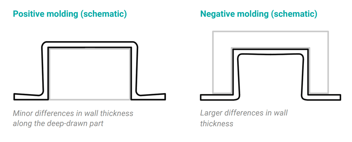
4. Design Rule: Positive vs. Negative Forming and Wall Thickness
The further or deeper the material is stretched into the tool during thermoforming, the thinner the remaining wall thickness becomes. Typically, the wall thickness to be achieved is determined, and then calculated backwards (see point 3) to determine how thick the starting material must be (so-called "reverse engineering").
Stretch & Draw Ratio
The stretch or draw ratio in thermoforming describes the length ratio of the material in the side profile (the initial thickness) and the thermoformed part. Generally: Positively formed parts result in a smaller and therefore more advantageous stretch ratio than negatively drawn parts with the same contour.
Important Rules During the Forming Process
Due to the viscoelastic behavior of thermoplastics during stretching, some rules of thumb must be observed during the forming process when designing plastic parts:
The colder the semi-finished product during stretching, the greater the force required to stretch it
The faster the deformation speed, the greater the force required to stretch it
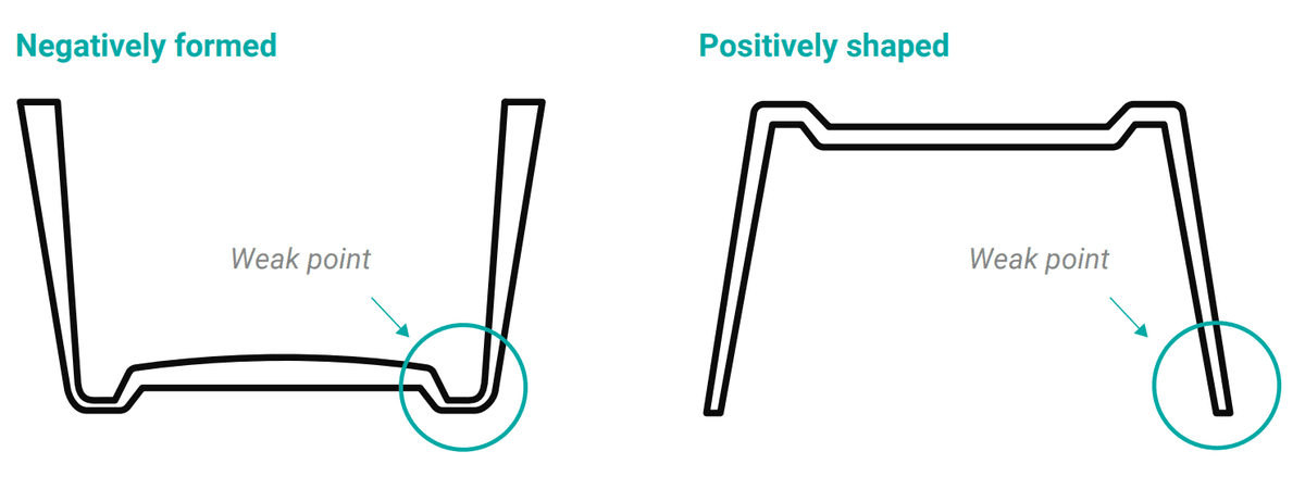
Positive Forming
With negatively formed parts, the weak point of the thermoformed part after forming is therefore in the base area, as material is stretched from the edge into the bottom of the tool cavity. The material thins out in the process.
Negative Forming
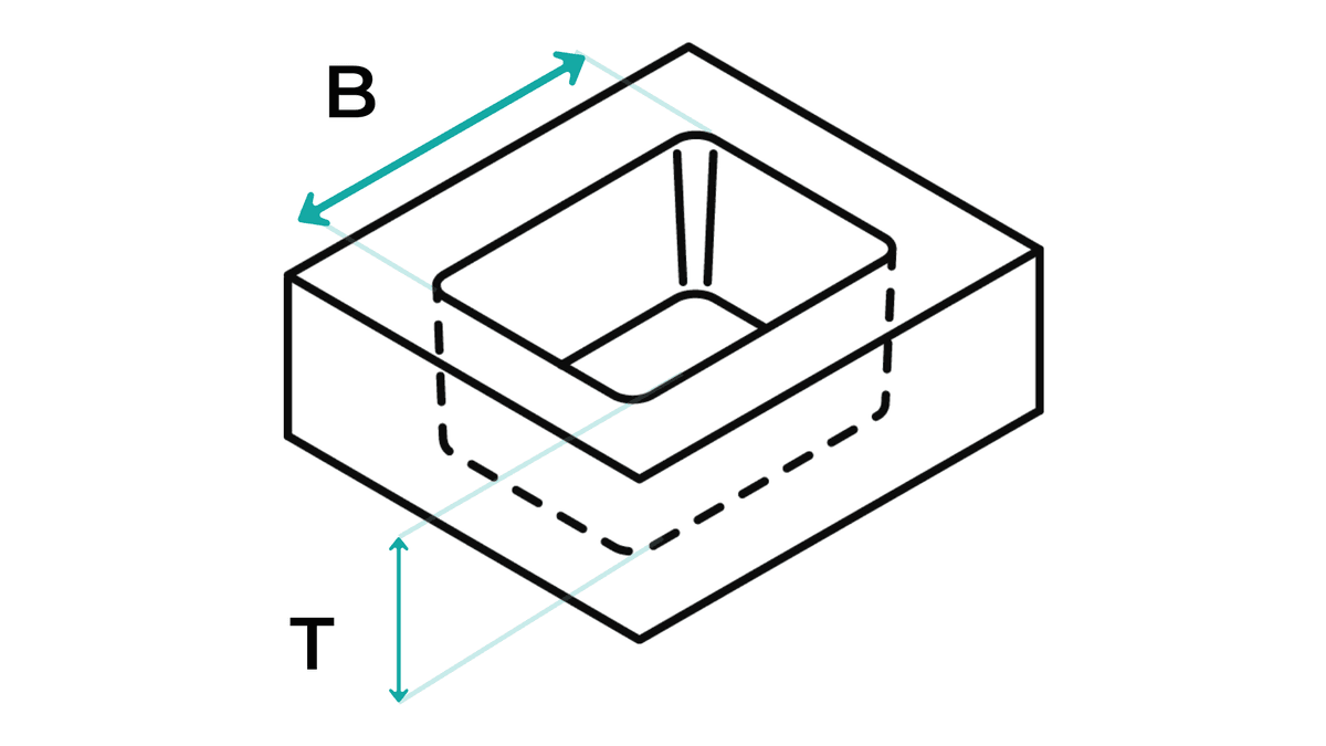
With positively formed parts, the weak point of the thermoformed part is at the edge, as the material first touches the positive tool at the base area of the future thermoformed part, thinning out the edge area downwards. Initial thicknesses chosen too thin and a poor forming ratio, i.e., the relation of opening width to opening depth, further exacerbate the negative effect.
For negative-formed cavities, the depth-to-width ratio should not exceed 1.5:1. A greater depth results in significant thinning, increasing the risk of rupture at the bottom edges.
The table explains the possibilities of different pull ratios for negative and positive shapes:
Forming Ratios for Negative and Positive Forms
Depth-to-Width Ratio
Positive Forming
Negative Forming
0.3:1
Possible
Possible
0.5:1
Possible
Needs punch assistance
1:1
Possible
Needs punch assistance
1.5:1
Material distortion at the limit
Material distortion at the limit
2:1
Must be tested; cannot be simulated
Must be tested; cannot be simulated
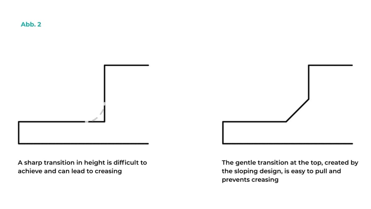
6. Design Rule: Transition Contours
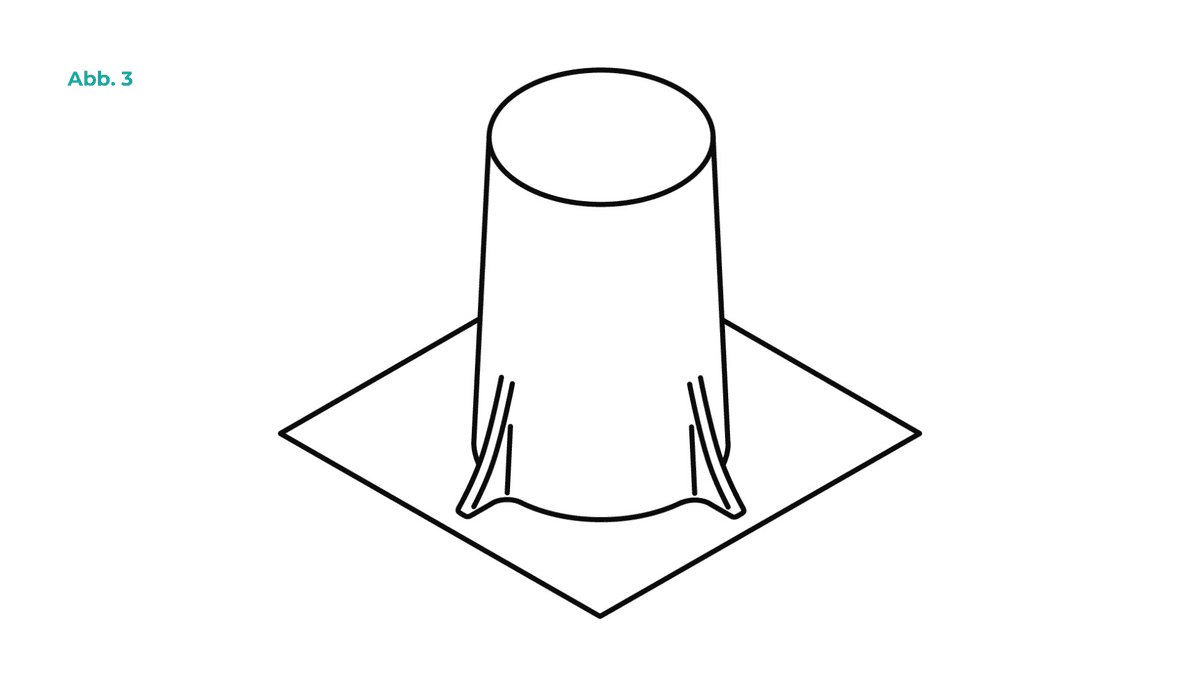
As already mentioned: In thermoforming design with plastics, it is essential to avoid small radii. Especially with precisely fitting component cavities, nests can be designed to be much more thermoformable with softened contours while maintaining full functionality.
Improved formability through softened contours
Figure 1 shows a cavity contour that is difficult to thermoform, while Figure 2 shows a softened contour that can be formed easily. By softening the draft angles and radii, the thermoformed part can be drawn more easily, which increases quality. Additionally, this minimizes the risk of tearing and guarantees higher reproducibility.
Benefits for production and costs
Ultimately, the cycle times are also shorter, which results in a generally welcome reduction in the unit price. Transitions from edge contours or stepped areas can also be smoothed out using chamfers.
Risks associated with small radii and possible solutions
If the radii are too small, there is always a risk of creasing during deep-drawing, particularly with positive moulds. To prevent creasing, ribbed transitions can also be incorporated into the plastic design to ensure that any creases that do occur during positive deep-drawing are at least controlled.
Creasing caused by subtle ribbing
7. Design Rule: Undercuts
Undercuts are features that prevent the part from being easily removed from the deep-drawing die. Unlike in injection moulding, there is no second die half, so they make demoulding more difficult.
Tips:
Avoid undercuts where possible, or reduce them to a level that allows for deep drawing.
Undercuts are often unavoidable in stacked components or clamping arrangements, so careful design is required.
ℹ️ Is your component suitable for deep-drawing?
Many design flaws originate in the CAD model and lead to higher costs or quality issues later on. We review your design and provide you with specific suggestions for optimisation to ensure cost-effective and reliable production.
8. Design Rule: Shrinkage During Processing
Bear in mind that processing shrinkage is a key factor in the design of a plastic deep-drawn part, as it affects the final dimensions and shape. After demoulding, the part shrinks further due to the material’s behaviour. This shrinkage varies depending on the material and can continue for up to 24 hours even after the part has cooled. In the case of semi-crystalline thermoplastics in particular, post-shrinkage never stops and the part may continue to shrink over time.
Measures to counteract processing shrinkage
Plan the tool size taking shrinkage into account.
Carry out a sample test before production begins.
Factors: choice of material, demoulding temperature, extrusion and internal stresses.
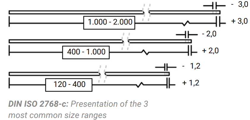
9. Design Rule: Thermoformable Tolerances
Deep-drawn parts are designed for most industrial and packaging applications with a tolerance of +/- ~1 mm. This corresponds to the tolerance range according to ISO 2768-c for the 120 to 400 mm length dimensions commonly used in this product area.
Forming tighter tolerances usually involves additional costs. These are due to longer demolding times, greater manufacturing costs, and/or longer cycle times.
ℹ️ It is important not to set tolerances unnecessarily tight: the motto “As large as possible, as small as necessary” serves as a general guideline in the design manual.
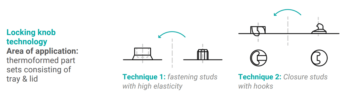
10. Design Rule: Fastening Points in Assemblies
Fixing points are required to assemble various deep-drawn parts or assemblies. Many fastening technology options are used to securely close deep-drawn parts. These must be carefully considered from the outset to ensure that the design is suitable for plastics. Depending on the mechanical load, the frequency of opening and closing, and the stability of the connection, various options are available for achieving a force-fit connection.
In permanently force-fit connections, screws or rivets are often attached to the deep-drawn parts at the transition points between two parts in order to achieve a connection.
11. Design Rule: Stacking Design
If your thermoformed part is to be stacked, this must be taken into account at an early stage of the design process to ensure that sufficient space is left for stacking. Several factors are key when selecting the appropriate stacking technique:
Initial material thickness
The choice of stacking method for a thermoformed part depends primarily on the part’s rigidity and the material’s sliding properties. The thicker the material (which is often the case with reusable trays), the easier it is to stack. The poorer the material’s sliding properties, the better the static friction, and consequently the easier it is to stack.
Sensitivity of the products
If the components are not allowed (or should not) be stacked on top of one another, but a gap of a few millimetres must be maintained, a higher-quality stacking technique is required. The reason for this is that the stack of thermoformed parts is self-supporting, meaning that the weight of the trays and their contents must be borne by the tray surface without any additional supports.
Urgency of the timetable
Complex stacking techniques involving movable stacking elements require the use of a flap mould. Manufacturing such a mould is more time-consuming than producing a relatively simple undercut stacking mould.
12. Design rule for thermoformed plastic parts: Material selection
Softer plastics exhibit greater deformation and higher processing shrinkage after demolding. Materials with high hardness and rigidity are automatically in a better tolerance group in terms of accuracy.
ℹ️ You can find out more about plastics, their properties and their impact on the overall costs of deep-drawing in our white paper Material Guide for Plastic Deep-Drawn Parts.
If you require markings on the thermoformed part, you are welcome to have these engraved directly into the mould.
Cost of engraving
The cost of engraving can vary considerably, depending on the type of engraving required. As a general rule, a recessed engraving is relatively inexpensive, whereas a raised engraving is considerably more labour-intensive and therefore more expensive.
Designing plastic parts: following the right guidelines for the best results
By following these basic design principles, potential sources of error can be avoided right from the design phase. This helps to reduce costs, minimises the need for iterative cycles and ensures safe production.
Would you like to ensure that your component is optimally designed for deep drawing? We would be happy to assist you with the design and implementation of your deep-drawn parts, and we recommend consulting our Design Guide for further guidance.
Frequently Asked Questions About the Design of Plastic Thermoformed Parts
Positive sections taper toward the edges, while negative sections taper toward the bottom. Positive shapes are generally more advantageous in terms of aspect ratio and material weaknesses.
Engravings: recessed (negative) ones are less expensive, while raised (positive) ones are more expensive. Fastening points such as screws or rivets should be planned early on, depending on the load and intended use.
Related content
Blog
Construction Data in Thermoforming: These Factors Must Be Considered for Plastic Deep Drawn Parts
Deep drawn parts are custom-made and designed individually in a CAD format. Before a deep drawing tool is manufactured, a customer approval process of the CAD data or the derived, dimensioned PDF drawing takes place.
Blog
Design for Manufacturing (DfM): Guide to Manufacturing-Oriented Design
With the new Design for Manufacturing analysis from formary, it is now possible to check CAD data for thermoformability in a matter of seconds, allowing potential sources of error to be identified early on before they become costly. Read on to find out what features the DfM software offers and what the Design for Manufacturing principle entails.
Blog
Thermoforming Tool for Plastic Thermoformed Parts: Structure, Types, and Manufacturing
Plastic thermoforming is a process in which a plastic sheet or film is heated and shaped over a mold to create various three-dimensional objects. A crucial element in the thermoforming process is the tooling used to achieve the desired shape.
Blog
Now live: Create Tray Designs Directly from CAD Data in Your Browser
Planning plastic trays for transport, storage, or automated manufacturing processes often starts with one key question: what should a suitable tray for the component actually look like? This is exactly what the new web-based 3D Tray Generator answers within seconds. Learn more in this article.